Saltar para o conteúdo
Power Inverters Explained - How do they work working principle IGBT|Leaptrend 2000W/4000W 12V to 220V Power Inverter on Camping Outdoor RV, Truck, Coffee Van, Caravan, Household Appliances, DC-AC Off-Grid Pure Sine Wave Solar Converter for Lithium LifePo4
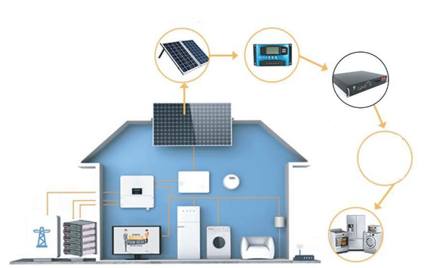
Inversores de energia são dispositivos eletrônicos que convertem energia CC (corrente contínua) em energia CA (corrente alternada). Eles desempenham um papel crucial no fornecimento de eletricidade para dispositivos e aparelhos que exigem energia CA quando não há acesso à rede elétrica ou quando uma fonte de energia portátil é necessária. Neste blog, explicaremos o princípio de funcionamento dos inversores de energia, com foco particular na tecnologia IGBT (Insulated Gate Bipolar Transistor). Princípio de funcionamento dos inversores de energia: O princípio básico de funcionamento de um inversor de energia envolve dois estágios: o estágio de conversão CC para CC e o estágio de conversão CC para CA. Conversão CC para CC: O primeiro estágio do inversor envolve a conversão da energia CC de entrada para um nível de tensão mais alto. Isso é normalmente obtido usando um circuito de comutação de alta frequência, como um conversor boost ou um conversor buck-boost. O objetivo deste estágio é aumentar ou ajustar o nível de tensão CC para o nível desejado necessário para o estágio de conversão CA subsequente. Conversão CC para CA: O segundo estágio do inversor é responsável por converter a tensão CC ajustada em energia CA. Este estágio utiliza dispositivos de comutação, como IGBTs ou MOSFETs (Metal-Oxide-Semiconductor Field-Effect Transistors), para gerar uma forma de onda CA de alta frequência. A forma de onda CA de alta frequência é então filtrada e moldada para produzir uma forma de onda de saída CA senoidal, semelhante à energia da rede. IGBTs em inversores de energia: IGBTs são comumente usados como os principais dispositivos de comutação em inversores de energia modernos. Eles combinam as vantagens de MOSFETs e transistores de junção bipolar (BJTs), tornando-os adequados para aplicações de alta potência. IGBTs têm uma porta controlada por tensão, permitindo fácil controle da operação de comutação. O IGBT opera como um dispositivo bipolar controlado por tensão. Ele consiste em uma estrutura semicondutora de três camadas, a saber, a camada N (emissor), camada P (base) e camada N+ (coletor). A camada N+ atua como o terminal de dreno para o fluxo de corrente. Durante a operação, quando uma tensão positiva é aplicada ao terminal do gate, ele cria um canal condutor entre o coletor e o emissor. Isso permite que a corrente flua através do IGBT, semelhante a um BJT. Quando a tensão do gate é reduzida ou removida, o IGBT desliga, interrompendo o fluxo de corrente. Em inversores de energia, os IGBTs são usados para ligar e desligar rapidamente a tensão de entrada CC em uma alta frequência, normalmente na faixa de vários quilohertz a várias dezenas de quilohertz. Essa ação de comutação cria uma série de pulsos de alta frequência, que são então filtrados e moldados para produzir uma forma de onda CA senoidal. Os IGBTs oferecem várias vantagens para inversores de energia, incluindo alta tensão e capacidades de manuseio de corrente, velocidades de comutação rápidas e baixas perdas de condução. Essas características tornam os IGBTs adequados para aplicações de alta potência, onde a conversão de energia eficiente e confiável é essencial. Concluindo, os inversores de energia funcionam convertendo energia CC em energia CA por meio de dois estágios: conversão CC para CC e conversão CC para CA. IGBTs são comumente usados como os principais dispositivos de comutação em inversores de energia devido às suas capacidades de alta tensão e manuseio de corrente, velocidades de comutação rápidas e baixas perdas de condução. Entender o princípio de funcionamento dos inversores de energia e o papel dos IGBTs pode ajudar na seleção e uso do inversor certo para várias aplicações.